In this post, I will show you how to deploy virtual Aruba AOS8 Mobility Controller in VMware ESXi and add it to a Mobility Conductor cluster. I used AOS version 8.6.0.15, but the steps should be the same for other 8.x versions. Check out this post and this post if you require assistance setting up your Mobility Conductors. If you have physical Mobility Controllers, skip to the Mobility Controller setup wizard section.
- Mobility Controller Virtual Machine Requirements
- Image Verification
- OVA Deployment
- Additional VM Settings
- Mobility Controller Setup Wizard
- Add Mobility Controllers to Mobility Conductors
Mobility Controller Virtual Machine Requirements
The table below shows the minimum resources required to operate Aruba AOS8 virtual Mobility Controllers on VMware ESXi.
| vCPUs | Memory | Disk Space | Total Supported NICs | |
| MC-VA-10 | 3 | 4GB | 6GB | 4 (3 Data, 1 MGMT) |
| MC-VA-50 | 4 | 6GB | 6GB | 4 (3 Data, 1 MGMT) |
| MC-VA-250 | 5 | 8GB | 8GB | 4 (3 Data, 1 MGMT) |
| MC-VA-1K | 6 | 16GB | 16GB | 4 (3 Data, 1 MGMT) |
| MC-VA-4K | 12 | 48GB | 48GB | 4 (3 Data, 1 MGMT) |
| MC-VA-6K | 14 | 64GB | 64GB | 4 (3 Data, 1 MGMT) |
*Note*
MC-VA-4K and MC-VA-6K are not orderable SKUs. However, you can scale up by installing multiple instances of MCVA-1K. For example, to deploy 4K APs on a single Mobility Controller Virtual Appliance, you need to add four MC-VA-1K licenses.
Image Verification
You must verify the MD5 or SHA256 checksum listed on the Aruba Support Portal to ensure it matches the computed checksum of the Mobility Controller ESXi image you downloaded. Don’t skip this step! There is nothing worse than having to re-download an image because it got corrupted somewhere along the way.
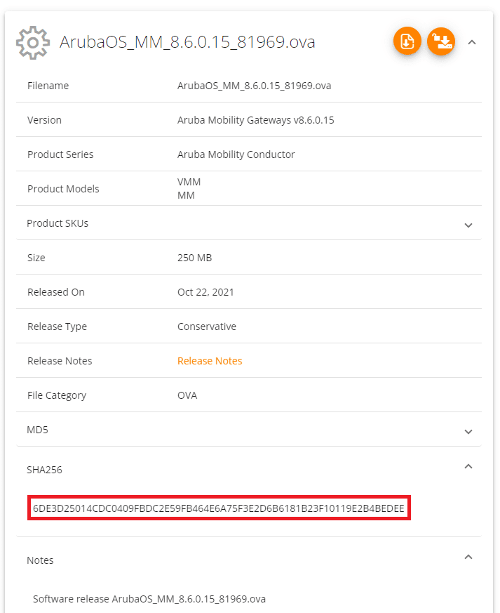
Using the PowerShell command cmdlet Get-FileHash I verified the SHA256 value:
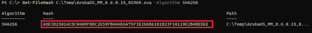
It’s a match! Otherwise, there are many GUI tools available if you prefer.
OVA Deployment
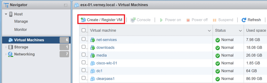
I access my ESXi console natively using HTTPS in my lab (no vSphere client).
First, we need to register the VM. Click Create / Register VM, and follow the prompts to select the image you downloaded from the Aruba Support Portal (ASP).
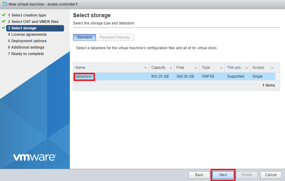
Select the storage where you want to install the VM and click Next.
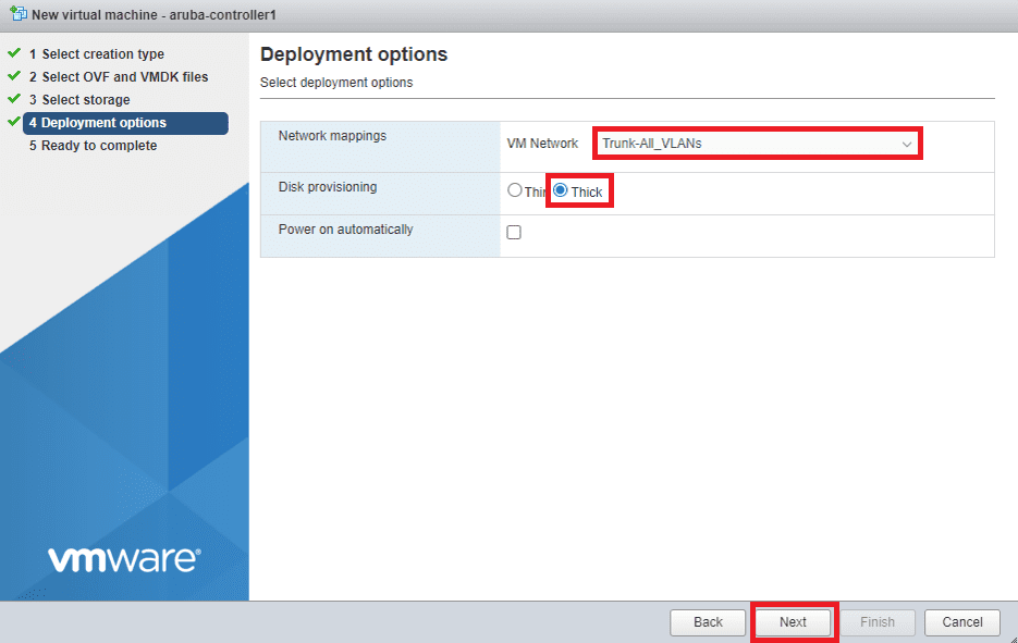
Map your Mobility Controller NICs to the appropriate VM network. I recommend using a VM port group that trunks/allows all VLANs (VLAN ID 4095) for scalability, but this choice boils down to one architectural decision. Do you plan on using your SSIDs in tunnel mode (client sessions terminate on the Controller)? Or do you plan on using your SSIDs in bridge mode (client sessions terminate on the switch connecting the APs. If the latter, technically, you only need to specify the management VLAN in this step.
Ensure Disk Provisioning is set to Thick. Untick the Power on automatically checkbox as we need to edit the VMs settings before it boots up.
Click Next to continue, then follow the prompts to confirm your setting and finalise the OVA deployment.
Additional VM Settings
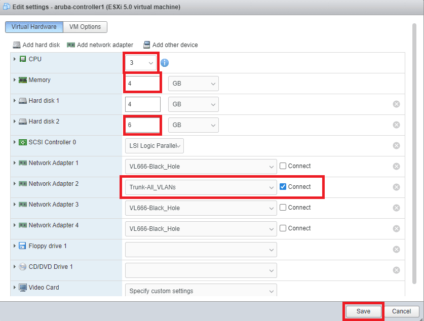
Before we power on the VM, there are a number of settings that we need to modify. When the VM has finished deploying, click on the Mobility Controller’s hostname in the list of VMs, select the Actions menu and click Edit settings.
Allocate the required CPU, RAM, and Hard Disk resources per the VM Requirements. Tick Reserve all guest memory (all locked) under the memory settings. Allocate the necessary hard disk space to the Hard disk 2. Hard disk one stores the OS and its base configuration, so don’t modify it.
I only require a single NIC, so have left Network Adaptor 2 allocated to my Trunk-All_VLANs Port Group. It is best practice to disable any unused NICs and place them in a VLAN that is unrouteable within the LAN in case of any misconfigurations. The four VM NICs correspond to the following Mobility Controller AOS8 NICs.
- Network Adaptor 1 – OOB Management
- Network Adaptor 2 – Gigabit Ethernet 0/0/0
- Network Adaptor 3 – Gigabit Ethernet 0/0/1
- Network Adaptor 4 – Gigabit Ethernet 0/0/2
Click Save to continue.
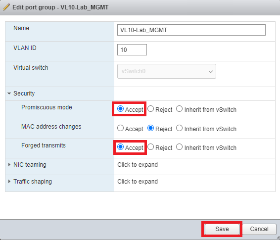
The next step is critical but is often skipped. I have seen it become the root cause of many early deployment issues, so don’t let it happen to you. Find and edit your global vSwitch settings or edit the port group that you used to connect your Mobility Controller. Expand the Security settings and enable Promiscuous Mode and Forged Transmits. Click Save to continue.
Find the Mobility Controller in the list of VMs and select Power On.
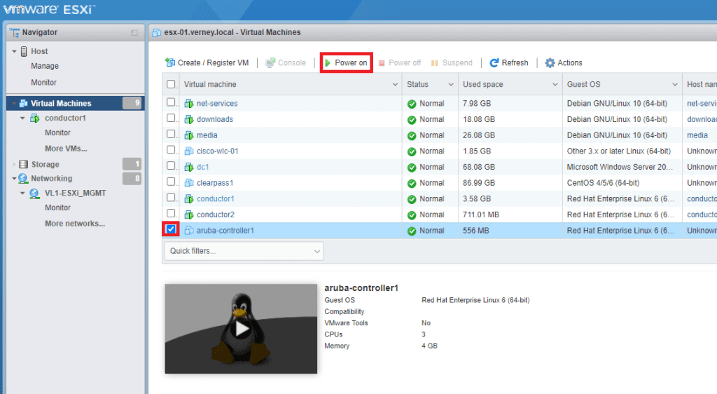
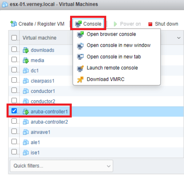
With your VM still selected, click Console and choose one of the available methods to access the VM.
Add Mobility Controllers to Mobility Masters
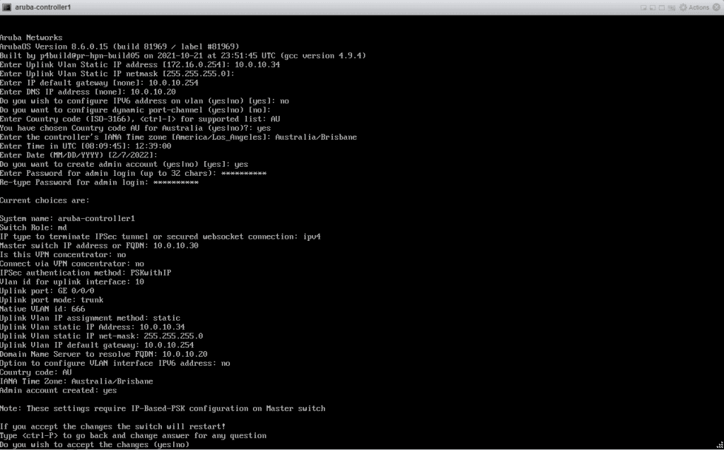
Once the Mobility Controller has finished booting, you will be presented with a setup wizard requiring you to enter the following details:
- System Name
- Switch Role (md/standalone)
- Mobility Conductor IP and IPSEC authentication type
- Port Mode (access/trunk)
- IP and Subnet Details
- DNS Server
- Location, date, and time details
- Local administrator credentials
You will be presented with an option to review and confirm the configuration. You must specify the correct Master Switch (Mobility Conductor) IP and IPSec details here because the Controllers will continuously attempt to build a secure tunnel to the Mobility Conductors from this point forward. Modifying those settings isn’t an easy task if it can’t join the Conductor. When you are happy with your provided details, type in yes and hit enter to accept the changes.
It will take time for the server to apply the changes and reboot, so be patient!
Add Mobility Controller to Mobility Conductors
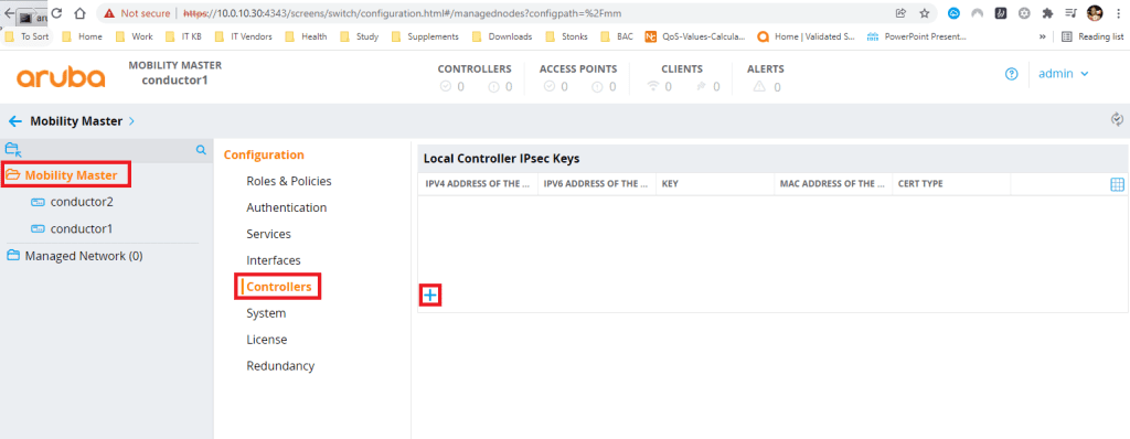
Navigate to your mobility Conductor cluster. Click on the Mobility Master Folder, click Configuration, Controllers then click the + sign.
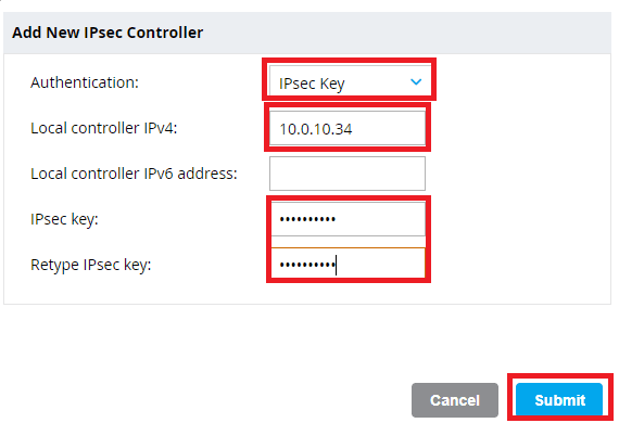
Enter the IP address and IPSec key of the first Mobility Controller
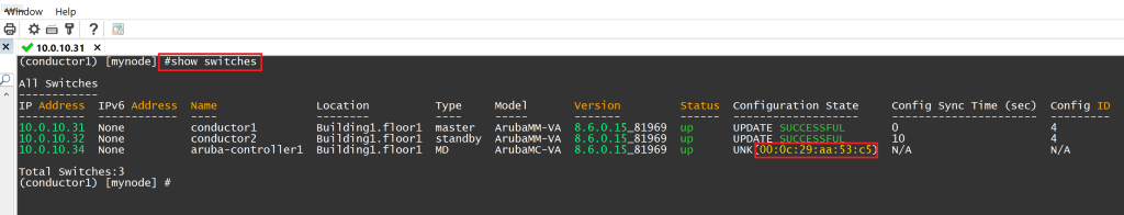
SSH to your primary Mobility Conductor and issue the command show switches. You should see your Controller in the unknown state while it attempts to build a tunnel to the Mobility Conductors. Copy the MAC address listed in the configuration state.
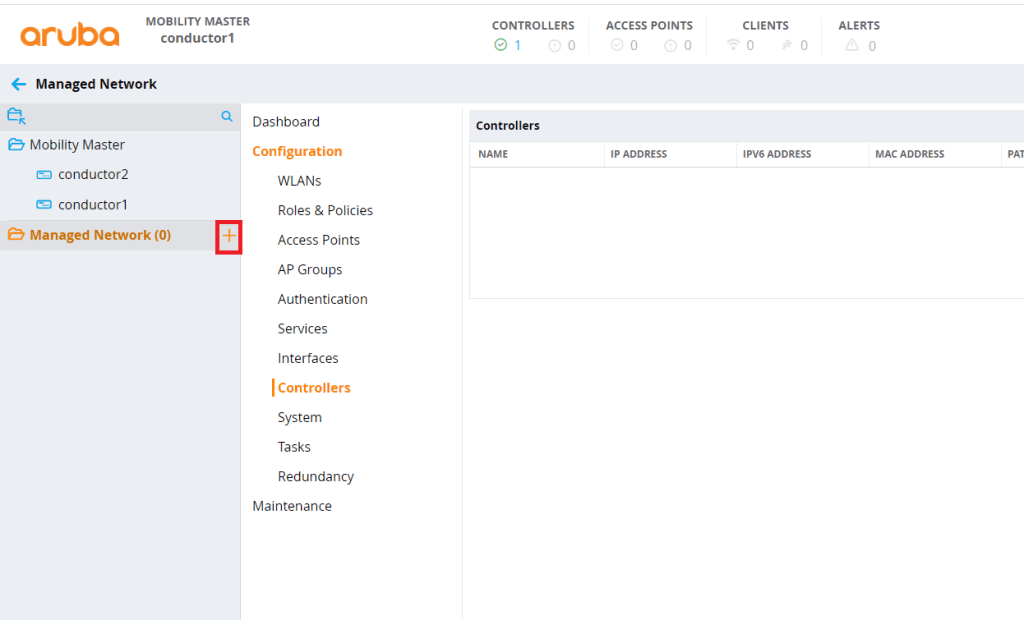
Head to your Mobility Conductor dashboard and click on the + sign next to Managed Network.
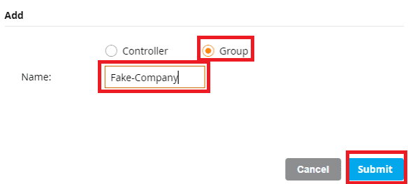
For the purpose of this demo, my managed network is going to consist of the following group structure. Managed Network –> Company Name –> City Name. I will place the Mobility Controllers in the City group folder. If the company expanded to other cities, I would place their Mobility Controllers in the groups of the cities that the Controllers physically reside in. Create the group folders that you desire and click Submit to continue.
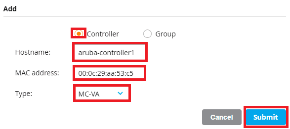
Select the group where you want your Mobility Controllers to reside in and click the + sign. This time, click Controller and enter the Hostname, MAC Address (that you copied in the previous step), and model of Controller. Click Submit to continue.
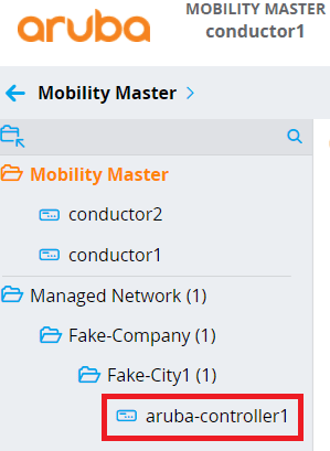
After some time, you should see your Mobility Controller appear in the group folder that you specified.
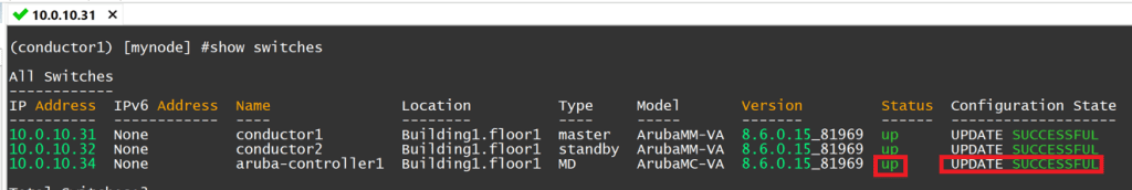
Head back to your Mobility Conductor’s SSH session, type in show switches again, and confirm that the Controller status is up and the Configuration State is successful.
I highly recommend adding a second Mobility Controller and forming a cluster to make use of the full range of HA and redundancy features that sets Aruba apart from other vendors. Repeat these steps to add the second Controller.